Found an issue with this page?
Edit on GitHub
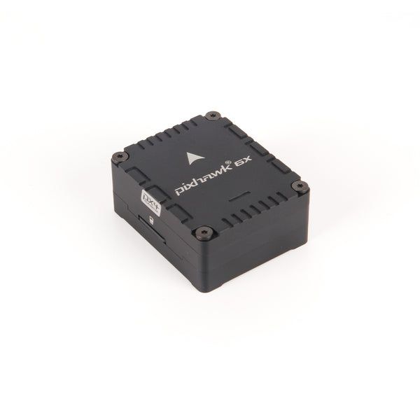
Holybro Pixhawk 6X
by Holybro
Community
Open Hardware
Pixhawk 6X ships as a core module paired with selectable baseboards for different payload integrations.
Key Specifications
Mounting Pattern
Cube Carrier Board
Connectivity
8 UARTs • 2 I²C • 2 CAN
Power
4.9–5.5 V • Power Module
Onboard Sensors
3× IMU • 2× Barometer • 1× Magnetometer
Firmware Support
Reference Docs
Detailed Specifications
Additional Features
Value-add capabilities bundled with the controller.- ✓ Ethernet companion computer link
- ✓ Modular baseboard ecosystem
- ✓ Triple-redundant inertial sensing
Core Specifications
Quick reference for the primary hardware capabilities.
| MCU | Mounting | Cube Carrier Board | |
| Power | 4.9–5.5 V • Power Module | I/O Overview | 8 UARTs • 2 I²C • 2 CAN |
| PWM & Storage | 16 PWM outputs • microSD logging | Sensors | 3× IMU • 2× Barometer • 1× Magnetometer |
Hardware Overview
Core MCU, mounting, and mechanical data.
Base hardware specification
Default
| MCU | Mounting | Cube Carrier Board | |
| Dimensions | 31.8 × 38.8 × 14.6 mm | Weight | 23g |
Power Supply
Input rails, regulators, and redundancy. Voltage —
Inputs 3
Redundancy Redundant
Power Inputs
POWER1 Power Module
Connector:
6-pin power monitor
Voltage:
4.9–5.5 V
POWER2 Power Module
Connector:
6-pin power monitor
Voltage:
4.9–5.5 V
USB USB
Connector:
USB Type-C
Voltage:
4.75–5.25 V
| Input Voltage | — | Redundancy | ✓ Yes |
Max input 6V on power ports with servo rail tolerance to 36V; triple-redundant POWER1/POWER2/USB inputs.
Connectivity & I/O
Port availability, buses, and expansion options.| UARTs | 8 | CAN Bus | 2 |
| PWM Outputs | 16 | SD Card | ✓ Yes |
| Ethernet | ✓ Yes | ||
Peripheral Ports
| Port | Type | Default Function | Voltage / Level | Connector | Notes |
|---|---|---|---|---|---|
| TELEM1 | UART | MAVLink telemetry (primary) | 3.3 V signal / 5 V supply | JST-GH 6-pin | Shared 5 V regulator with TELEM2; supports hardware flow control. |
| TELEM2 | UART | Companion computer or RTK corrections | 3.3 V signal / 5 V supply | JST-GH 6-pin | Ideal for high-bandwidth MAVLink or RTK radios. |
| TELEM3 | UART | Payload or scripting UART | 3.3 V signal | JST-GH 6-pin | Routed through carrier board; configurable via SERIAL3 parameters. |
| TELEM4 | UART | Secondary telemetry | 3.3 V signal | JST-GH 6-pin | Shares power rail with TELEM3; supports TTL-level peripherals only. |
| TELEM5 | UART | Debug console / ESC telemetry | 3.3 V signal | JST-GH 6-pin | Labeled "FMU Debug" on carrier; defaults to system console in PX4. |
| GPS1 | GPS | Primary GPS/compass/safety switch | 3.3 V signal / 5 V supply | JST-GH 10-pin | Combined connector with safety switch, buzzer, and I2C compass harness. |
| GPS2 | GPS | Secondary GPS | 3.3 V signal / 5 V supply | JST-GH 6-pin | Secondary navigation receiver header for redundancy or RTK base station links. |
| CAN1 | CAN | DroneCAN peripheral bus | Differential CAN / 5 V supply | JST-GH 4-pin | Powered CAN-FD port for smart power modules, ESCs, or payloads. |
| CAN2 | CAN | Redundant CAN-FD bus | Differential CAN / 5 V supply | JST-GH 4-pin | Second CAN interface supporting ESC RX-MUX and payload networks. |
| I2C1 | I2C | Auxiliary sensor bus | 3.3 V | JST-GH 4-pin | External I2C lines for airspeed sensors, compasses, or LED expanders. |
| POWER1 | Power | Primary power module | 4.9-5.5 V | 6-pin power monitor | Supplies regulated 5 V and SMBus telemetry from the first power module. |
| POWER2 | Power | Secondary power module | 4.9-5.5 V | 6-pin power monitor | Provides redundant power and SMBus battery data when paired with a second module. |
| SERVO RAIL | Power | PWM servo supply | 0-36 V tolerant | Servo breakout | High-voltage tolerant rail powering PWM outputs independently from FMU logic. |
| FMU PWM OUT (1-8) | PWM | Primary motor outputs | Servo rail (0-36 V tolerant) | Servo breakout bank A | FMU-controlled DShot/PWM outputs grouped for synchronous signaling. |
| IO PWM OUT (9-16) | PWM | Auxiliary PWM outputs | Servo rail (0-36 V tolerant) | Servo breakout bank B | IOMCU-managed outputs for additional motors, gear, or payload servos. |
| RCIN | RC | Serial RC or PPM input | 3.3 V signal / 5 V supply | JST-GH 6-pin | Supports SBUS, DSM, FPort, CRSF, and PPM receiver connections. |
| S.BUS OUT / RSSI | RC | S.Bus out and analog RSSI | 3.3 V signal | JST harness | Provides redundant receiver output and RSSI monitoring for ground stations. |
| USB-C | USB | Console and firmware updates | 5 V | USB Type-C | Primary configuration interface and bootloader access. |
| Ethernet | Ethernet | 100 Mbps companion link | 3.3 V logic | RJ45 breakout | On supported carrier boards, exposes the integrated Ethernet PHY for companion computers. |
| I2C Expansion (UART breakout) | I2C | Additional I2C via TELEM3/4 harness | 3.3 V | JST-GH 6-pin shared | TELEM3/4 harness exposes SCL/SDA pins for auxiliary digital sensors. |
| Buzzer/Safety | Other | External safety switch and buzzer | 5 V supply | JST harness | Combined harness powering the safety switch, RGB LED, and high-output buzzer module. |
| TELEM6 | UART | Auxiliary telemetry / SBUS out | 3.3 V signal | JST-GH 6-pin | Supports serial RC protocols or additional MAVLink link. |
| GPS1 | GPS | Primary GNSS + compass + safety switch | 5 V supply / 3.3 V I2C | JST-GH 10-pin | Carries I2C for compass and safety switch passthrough. |
| GPS2 | GPS | Redundant GNSS + compass | 5 V supply / 3.3 V I2C | JST-GH 6-pin | Provides backup GPS with integrated I2C lines. |
| I2C1 | I2C | Magnetometer / Airspeed bus | 3.3 V | JST-GH 4-pin | Shares bus with GPS headers; do not mix 5 V I2C devices. |
| I2C2 | I2C | External sensors expansion | 3.3 V | JST-GH 4-pin | Routed to carrier board expansion header for payload sensors. |
| CAN1 | CAN | DroneCAN node bus | 5 V accessory power | JST-GH 4-pin | Provides regulated 5 V for smart peripherals up to 1 A shared. |
| CAN2 | CAN | Redundant DroneCAN bus | 5 V accessory power | JST-GH 4-pin | Isolated from CAN1 for dual-redundant power modules. |
| POWER1 | Power | Primary power module input | 4.9–5.5 V | 6-pin power monitor | Supports Holybro PM06/PM07 modules with SMBus telemetry. |
| POWER2 | Power | Redundant power module input | 4.9–5.5 V | 6-pin power monitor | Backup BEC feed with current/voltage sense. |
| USB-C | USB | Console / firmware update | 5 V USB | USB Type-C | Supplies cube when no external BEC is present; limited to 1 A. |
| RCIN/SBUS | RC | Serial RC receiver input | 3.3 V signal / 5 V supply | JST-GH 6-pin | Compatible with SBUS, CRSF, and DSM protocols via configuration. |
Onboard Sensors
IMU, barometer, and magnetometer load-outs per revision.| IMU | |||
| Barometer | |||
| Magnetometer | |||
Known Issues & Advisories
Pixhawk 6X Rev8 reports dead TELEM1 on PX4 1.14 builds
Multiple Pixhawk 6X Rev8 units shipped with PX4 1.14.x exhibit a non-functional TELEM1 port, RC input failures, and motors that refuse to arm until firmware is downgraded.
High
BMI088 I²C driver produces unstable gyro data
PX4's bmi088_i2c driver reports severe gyro jitter and unusable orientation on Crazyflie and other I²C-based boards.
Medium
Reported
Affects Bosch Sensortec BMI088
Onboard IMU
Documentation & Vendor Resources
Contributors: dependabot[bot]
Last updated:
View History