Found an issue with this page?
Edit on GitHub
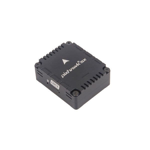
Holybro Pixhawk 5X
by Holybro
Community
Closed Hardware
ArduPilot notes integrated Ethernet hardware is present but disabled on the STM32F7 platform firmware.
Key Specifications
Mounting Pattern
Cube Carrier Board
Connectivity
8 UARTs • 2 I²C • 2 CAN
Power
4.75–6 V • Power Module
Onboard Sensors
3× IMU • 2× Barometer • 1× Magnetometer
Firmware Support
Detailed Specifications
Additional Features
Value-add capabilities bundled with the controller.- ✓ Integrated Ethernet interface (not enabled on F7 firmware)
- ✓ Triple-redundant IMUs with vibration isolation and heating
- ✓ Two CAN buses with dedicated power monitor inputs
Core Specifications
Quick reference for the primary hardware capabilities.
| MCU | Mounting | Cube Carrier Board | |
| Power | 4.75–6 V • Power Module | I/O Overview | 8 UARTs • 2 I²C • 2 CAN |
| PWM & Storage | 16 PWM outputs • no microSD slot | Sensors | 3× IMU • 2× Barometer • 1× Magnetometer |
Hardware Overview
Core MCU, mounting, and mechanical data.
Base hardware specification
Default
| MCU | Mounting | Cube Carrier Board | |
| Dimensions | 31.8 × 38.8 × 14.6 mm | Weight | 23g |
Power Supply
Input rails, regulators, and redundancy. Voltage —
Inputs 4
Redundancy Redundant
Power Inputs
POWER1 Power Module
Connector:
6-pin power monitor
Voltage:
4.75–6 V
POWER2 Power Module
Connector:
6-pin power monitor
Voltage:
4.75–6 V
USB USB
Connector:
Micro-USB
Voltage:
4.75–5.25 V
SERVO_RAIL Servo Rail
Voltage:
0–36 V
High-voltage tolerant servo rail passthrough
| Input Voltage | — | Redundancy | ✓ Yes |
Dual SMBus power ports with high-voltage tolerant servo rail and optional USB power.
Connectivity & I/O
Port availability, buses, and expansion options.| UARTs | 8 | CAN Bus | 2 |
| PWM Outputs | 16 | SD Card | ✗ No |
| Ethernet | ✓ Yes | ||
Peripheral Ports
| Port | Type | Default Function | Voltage / Level | Connector | Notes |
|---|---|---|---|---|---|
| TELEM1 | UART | Primary MAVLink telemetry | 3.3 V signal / 5 V @ 1.5 A peripheral power | JST-GH 6-pin | DMA-enabled serial port with hardware flow control and highest current 5 V rail. |
| TELEM2 | UART | Secondary telemetry link | 3.3 V signal / 5 V supply | JST-GH 6-pin | Full RTS/CTS UART suited to long-range radios or RTK corrections. |
| TELEM3 | UART | Configurable serial payload bus | 3.3 V signal / 5 V supply | JST-GH 6-pin | UART2 port typically reassigned to scripting engines, ESC telemetry, or serial RC receivers. |
| USER UART4 | UART | Auxiliary UART for payloads or RC | 3.3 V signal | JST-GH 6-pin | UART4 header with shared GPIO for RSSI/FPort wiring. |
| GPS1 | GPS | Primary GPS/compass/safety harness | 3.3 V signal / 5 V supply | JST-GH 10-pin | Includes safety switch, buzzer, and I2C compass wiring. |
| GPS2 | GPS | Secondary GPS | 3.3 V signal / 5 V supply | JST-GH 6-pin | Provides redundant navigation receiver interface. |
| CAN1 | CAN | DroneCAN peripheral bus | Differential CAN / 5 V supply | JST-GH 4-pin | Powers smart modules such as ESCs or GPS with CAN-FD support. |
| CAN2 | CAN | Redundant CAN network | Differential CAN / 5 V supply | JST-GH 4-pin | Enables second CAN segment or ESC daisy-chain. |
| I2C1 | I2C | Auxiliary sensor bus | 3.3 V | JST-GH 4-pin | Shared with GPS harness for magnetometers or digital peripherals. |
| I2C2 | I2C | External I2C expansion | 3.3 V | JST-GH 4-pin | Dedicated side-panel connector for airspeed sensors or rangefinders. |
| RCIN | RC | Primary receiver input | 3.3 V signal / 5 V supply | JST-GH 6-pin | Supports PPM, SBUS, DSM, FPort, and CRSF protocols with dedicated RSSI pin. |
| S.BUS OUT / RSSI | RC | S.Bus passthrough and analog RSSI | 3.3 V signal | JST-GH 3-pin | Provides redundant receiver output and RSSI monitoring for ground stations. |
| FMU PWM OUT (1-8) | PWM | Primary motor outputs | Servo rail (0-36 V tolerant) | Servo rail bank A | FMU-controlled outputs supporting DShot on all groups except 7-8. |
| IO PWM OUT (9-16) | PWM | Auxiliary PWM outputs | Servo rail (0-36 V tolerant) | Servo rail bank B | IOMCU-managed outputs for secondary actuators or camera triggers. |
| POWER1 | Power | Primary power module input | 4.75-6.0 V | 6-pin power monitor | SMBus-enabled connector for current/voltage telemetry and redundant 5 V supply. |
| POWER2 | Power | Secondary power module input | 4.75-6.0 V | 6-pin power monitor | Backup SMBus power input for redundant supply architectures. |
| SERVO RAIL | Power | PWM servo supply | 0-36 V tolerant | Servo rail bus | High-voltage tolerant servo power isolated from FMU electronics. |
| Micro-USB | USB | Console and firmware updates | 5 V | Micro-USB | Provides SERIAL0 console, bootloader, and SLCAN access. |
| Ethernet | Ethernet | 100 Mbps companion link | 3.3 V logic | RJ45 breakout | Disabled in STM32F7 firmware but fully routed to the RJ45 breakout board. |
| FMU Debug | Debug | SWD + system console | 3.3 V | JST-GH 6-pin | Provides SWDIO/SWCLK and UART console for firmware development. |
Onboard Sensors
IMU, barometer, and magnetometer load-outs per revision.| IMU | |||
| Barometer | |||
| Magnetometer | |||
Known Issues & Advisories
No documented issues for Base Hardware
Sensor advisories and controller errata for this revision will appear here once reported.
Documentation & Vendor Resources
Contributors: dependabot[bot]
Last updated:
View History