Found an issue with this page?
Edit on GitHub
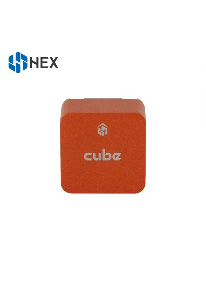
CubePilot Cube Orange+
by CubePilot
Community
Open Hardware
Cube Orange+ ships as a modular cube requiring a compatible carrier board for IO breakout.
Key Specifications
Mounting Pattern
Cube Carrier Board
Connectivity
5 UARTs • 1 I²C • 2 CAN
Power
4.1–5.7 V • Power Module
Onboard Sensors
3× IMU • 2× Barometer • 2× Magnetometer
Firmware Support
Reference Docs
Detailed Specifications
Additional Features
Value-add capabilities bundled with the controller.- ✓ ADS-B carrier compatibility
- ✓ Integrated vibration isolation
- ✓ Redundant power inputs
Core Specifications
Quick reference for the primary hardware capabilities.
| MCU | Mounting | Cube Carrier Board | |
| Power | 4.1–5.7 V • Power Module | I/O Overview | 5 UARTs • 1 I²C • 2 CAN |
| PWM & Storage | 14 PWM outputs • microSD logging | Sensors | 3× IMU • 2× Barometer • 2× Magnetometer |
Hardware Overview
Core MCU, mounting, and mechanical data.
Base hardware specification
Default
| MCU | Mounting | Cube Carrier Board | |
| Dimensions | 38.25 × 38.25 × 22.3 mm | Weight | — |
Power Supply
Input rails, regulators, and redundancy. Voltage —
Inputs 3
Redundancy Redundant
Power Inputs
POWER1 Power Module
Connector:
6-pin power monitor
Voltage:
4.1–5.7 V
POWER2 Power Module
Connector:
6-pin power monitor
Voltage:
4.1–5.7 V
USB USB
Connector:
Micro-USB
Voltage:
4.75–5.25 V
| Input Voltage | — | Redundancy | ✓ Yes |
POWER inputs 4.1-5.7V with redundant supply and USB input 4.75-5.25V.
Connectivity & I/O
Port availability, buses, and expansion options.| UARTs | 5 | CAN Bus | 2 |
| PWM Outputs | 14 | SD Card | ✓ Yes |
| Ethernet | ✗ No | ||
Peripheral Ports
| Port | Type | Default Function | Voltage / Level | Connector | Notes |
|---|---|---|---|---|---|
| TELEM1 | UART | Primary MAVLink telemetry | 3.3 V signal / 5 V supply | JST-GH 6-pin | Full RTS/CTS telemetry port powering radios or companion computers. |
| TELEM2 | UART | Secondary telemetry or RTK link | 3.3 V signal / 5 V supply | JST-GH 6-pin | Second hardware flow-control port for redundant radios or payload links. |
| GPS1 | GPS | Primary GPS/compass/safety harness | 3.3 V signal / 5 V supply | JST-GH 10-pin | Integrates safety switch, buzzer, and LED wiring with the first GNSS receiver. |
| GPS2 | GPS | Secondary GPS | 3.3 V signal / 5 V supply | JST-GH 6-pin | Provides redundant GNSS interface or alternative UART/I2C combination. |
| CAN1 | CAN | DroneCAN peripheral bus | Differential CAN / 5 V supply | JST-GH 4-pin | Powered CAN-FD connector for smart nodes, ESCs, or power modules. |
| CAN2 | CAN | Redundant DroneCAN bus | Differential CAN / 5 V supply | JST-GH 4-pin | Second CAN interface for redundant networks or payloads. |
| I2C | I2C | External sensor bus | 3.3 V | JST-GH 4-pin | Shared I2C bus for magnetometers, airspeed sensors, or peripheral hubs. |
| ADC | Analog | Differential pressure / analog sensing | 0-3.3 V | JST-GH 3-pin | Analog input with reference and ground for secondary battery or pitot sensors. |
| RCIN | RC | Serial RC input | 3.3 V signal / 5 V supply | JST-GH 6-pin | Supports CPPM, SBUS, and Spektrum receivers with dedicated power and RSSI pins. |
| PWM OUT (1-8) | PWM | Primary servo outputs | Servo rail (0-36 V tolerant) | Carrier board servo rail | IOMCU-managed outputs for actuators, landing gear, or camera gimbals. |
| PWM OUT (9-14) | PWM | FMU aux outputs | Servo rail (0-36 V tolerant) | Carrier board aux rail | FMU-controlled outputs supporting DShot on compatible channels. |
| POWER1 | Power | Primary power module input | 4.1-5.7 V | 6-pin power monitor | Provides regulated 5 V with current and voltage telemetry. |
| POWER2 | Power | Secondary power module input | 4.1-5.7 V | 6-pin power monitor | Redundant power module connection for high-reliability builds. |
| SERVO RAIL | Power | Servo rail supply | 0-36 V tolerant | Servo rail bus | High-voltage tolerant rail powering PWM outputs separately from logic supply. |
| Micro-USB | USB | Console and firmware updates | 5 V | Micro-USB | Provides SERIAL0 console and bootloader access via the carrier board harness. |
| ADS-B Serial5 | UART | Integrated ADS-B receiver | 3.3 V signal | Internal carrier connection | Dedicated Serial5 link from the carrier board’s uAvionix ADS-B receiver to the cube core. |
Onboard Sensors
IMU, barometer, and magnetometer load-outs per revision.| IMU | |||
| Barometer | |||
| Magnetometer | |||
Known Issues & Advisories
No documented issues for Base Hardware
Sensor advisories and controller errata for this revision will appear here once reported.
Documentation & Vendor Resources
Contributors: dependabot[bot]
Last updated:
View History