Found an issue with this page?
Edit on GitHub
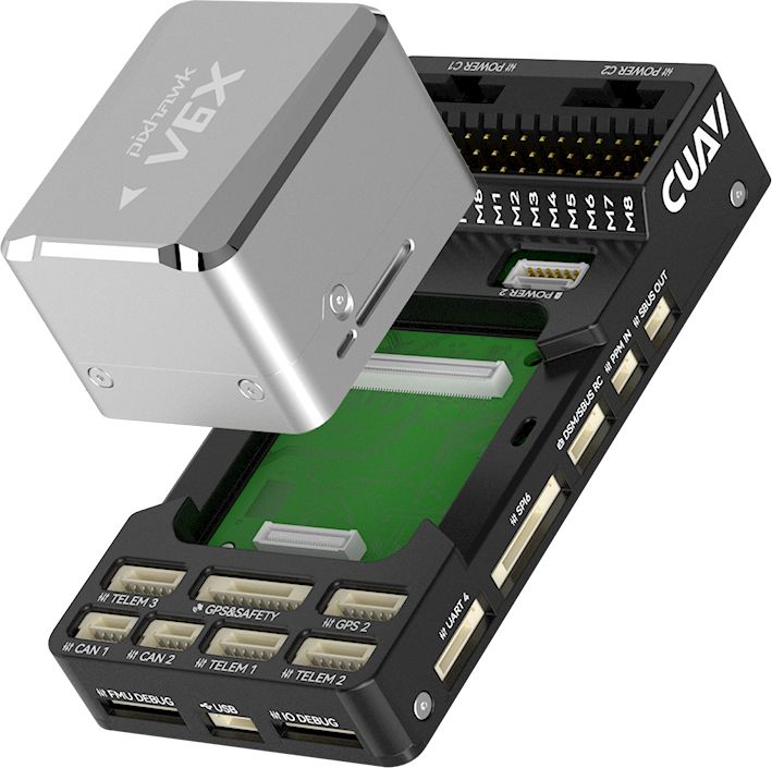
CUAV Pixhawk v6X
by CUAV
Community
Open Hardware
Ships with a heat-dissipating aluminum enclosure and CAN power module in the box.
Key Specifications
Mounting Pattern
Cube Carrier Board
Connectivity
8 UARTs • 1 SPI • 2 CAN
Power
4.9–5.5 V • Power Module
Onboard Sensors
3× IMU • 2× Barometer • 1× Magnetometer
Firmware Support
ArduPilot
PX4 Autopilot
Detailed Specifications
Additional Features
Value-add capabilities bundled with the controller.- ✓ CAN power module support
- ✓ Ethernet mission computer link
- ✓ Triple-redundant IMU domains
Core Specifications
Quick reference for the primary hardware capabilities.
| MCU | Mounting | Cube Carrier Board | |
| Power | 4.9–5.5 V • Power Module | I/O Overview | 8 UARTs • 1 SPI • 2 CAN |
| PWM & Storage | 16 PWM outputs • microSD logging | Sensors | 3× IMU • 2× Barometer • 1× Magnetometer |
Hardware Overview
Core MCU, mounting, and mechanical data.
Base hardware specification
Default
| MCU | Mounting | Cube Carrier Board |
Power Supply
Input rails, regulators, and redundancy. Voltage —
Inputs 1
Redundancy Redundant
Power Inputs
POWER1 Power Module
Connector:
CAN/SMBus power modules
Voltage:
4.9–5.5 V
| Input Voltage | — | Redundancy | ✓ Yes |
Dual SMBus/I2C power module inputs with CAN power module included; servo rail tolerant to 36V.
Connectivity & I/O
Port availability, buses, and expansion options.| UARTs | 8 | CAN Bus | 2 |
| PWM Outputs | 16 | SD Card | ✓ Yes |
| Ethernet | ✓ Yes | ||
Peripheral Ports
| Port | Type | Default Function | Voltage / Level | Connector | Notes |
|---|---|---|---|---|---|
| TELEM1 | UART | Primary MAVLink telemetry | 3.3 V signal / 5 V @ 1.5 A peripheral power | JST-GH 6-pin | High-current regulator for telemetry radios or companion computers with hardware flow control. |
| TELEM2 | UART | Secondary telemetry link | 3.3 V signal / 5 V supply | JST-GH 6-pin | Full RTS/CTS UART for redundant radios, RTK corrections, or payload links. |
| TELEM3 | UART | Configurable serial payload bus | 3.3 V signal / 5 V supply | JST-GH 6-pin | Assignable UART commonly used for scripting engines or serial RC receivers. |
| GPS1 | GPS | Primary GPS/compass/safety harness | 3.3 V signal / 5 V supply | JST-GH 10-pin | Includes safety switch, buzzer, and I2C compass wiring for the first GNSS unit. |
| GPS2 | GPS | Secondary GPS or telemetry | 3.3 V signal / 5 V supply | JST-GH 6-pin | Provides redundant GNSS interface or alternate UART with shared I2C breakout. |
| CAN1 | CAN | DroneCAN peripheral bus | Differential CAN / 5 V supply | JST-GH 4-pin | Powered CAN-FD connector for smart power modules, ESCs, or payload nodes. |
| CAN2 | CAN | Redundant DroneCAN bus | Differential CAN / 5 V supply | JST-GH 4-pin | Supports second CAN segment or ESC daisy-chain with switchable 5 V feed. |
| SPI6 | SPI | External payload SPI | 3.3 V | JST-GH 6-pin | Breaks out SPI6 with chip-selects for high-rate sensors or data loggers. |
| RCIN | RC | Serial RC input (SBUS/CRSF/FPort) | 3.3 V signal / 5 V supply | JST-GH 6-pin | Timer-capable input supporting PWM/PPM and serial receiver protocols. |
| FMU PWM OUT (1-8) | PWM | Primary motor outputs | Servo rail (0-36 V tolerant) | Servo breakout bank A | FMU-controlled outputs supporting DShot across grouped channels. |
| IO PWM OUT (9-16) | PWM | Auxiliary PWM outputs | Servo rail (0-36 V tolerant) | Servo breakout bank B | IOMCU-managed outputs for secondary motors, retracts, or camera triggers. |
| POWER1 | Power | Primary power module input | 4.9-5.5 V | 6-pin SMBus power module | SMBus-enabled power module supplying redundant 5 V and battery telemetry. |
| POWER2 | Power | Secondary power module input | 4.9-5.5 V | 6-pin SMBus power module | Secondary SMBus connector for redundant power module or smart battery. |
| SERVO RAIL | Power | PWM servo supply | 0-36 V tolerant | Servo rail bus | High-voltage tolerant rail powering PWM outputs separate from logic supply. |
| USB-C (remote) | USB | Console and firmware updates | 5 V | Remote-mounted USB Type-C | Includes detachable harness for in-airframe access to SERIAL0 console. |
| Ethernet | Ethernet | 100 Mbps companion link | 3.3 V logic | RJ45 breakout | Provides high-bandwidth link to companion computers via included breakout. |
| Buzzer/Safety | Other | External safety switch and buzzer | 5 V supply | JST harness | Combined harness powering the safety button, RGB LED, and audible buzzer module. |
Onboard Sensors
IMU, barometer, and magnetometer load-outs per revision.| IMU | |||
| Barometer | |||
| Magnetometer | |||
Known Issues & Advisories
BMI088 I²C driver produces unstable gyro data
PX4's bmi088_i2c driver reports severe gyro jitter and unusable orientation on Crazyflie and other I²C-based boards.
Medium
Reported
Affects Bosch Sensortec BMI088
Onboard IMU
Documentation & Vendor Resources
Contributors: dependabot[bot]
Last updated:
View History