Found an issue with this page?
Edit on GitHub
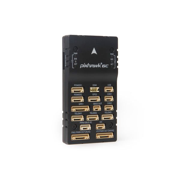
Holybro Pixhawk 6C
by Holybro
Community
Open Hardware
Pixhawk 6C ships in plastic or aluminum enclosures with optional bundled power modules.
Key Specifications
Mounting Pattern
Cube Carrier Board
Connectivity
7 UARTs • 2 I²C • 2 CAN
Power
4.9–5.5 V • Power Module
Onboard Sensors
2× IMU • 1× Barometer • 1× Magnetometer
Firmware Support
Reference Docs
Detailed Specifications
Additional Features
Value-add capabilities bundled with the controller.- ✓ Hardware-selectable PWM signal voltage
- ✓ Integrated vibration isolation
- ✓ Redundant IMU stack
Core Specifications
Quick reference for the primary hardware capabilities.
| MCU | Mounting | Cube Carrier Board | |
| Power | 4.9–5.5 V • Power Module | I/O Overview | 7 UARTs • 2 I²C • 2 CAN |
| PWM & Storage | 16 PWM outputs • microSD logging | Sensors | 2× IMU • 1× Barometer • 1× Magnetometer |
Hardware Overview
Core MCU, mounting, and mechanical data.
Base hardware specification
Default
| MCU | Mounting | Cube Carrier Board | |
| Dimensions | 44 × 84.8 × 12.4 mm | Weight | 59.3g |
Power Supply
Input rails, regulators, and redundancy. Voltage —
Inputs 3
Redundancy Redundant
Power Inputs
POWER1 Power Module
Connector:
6-pin power monitor
Voltage:
4.9–5.5 V
POWER2 Power Module
Connector:
6-pin power monitor
Voltage:
4.9–5.5 V
USB USB
Connector:
USB Type-C
Voltage:
4.75–5.25 V
| Input Voltage | — | Redundancy | ✓ Yes |
Max input 6V with 0-36V servo rail tolerance; triple-redundant POWER1/POWER2/USB inputs.
Connectivity & I/O
Port availability, buses, and expansion options.| UARTs | 7 | CAN Bus | 2 |
| PWM Outputs | 16 | SD Card | ✓ Yes |
| Ethernet | ✗ No | ||
Peripheral Ports
| Port | Type | Default Function | Voltage / Level | Connector | Notes |
|---|---|---|---|---|---|
| TELEM1 | UART | Primary MAVLink telemetry | 3.3 V signal / 5 V @ 1.5 A peripheral power | JST-GH 6-pin | Dedicated 1.5 A regulator powers telemetry radios or companion computers. |
| TELEM2 | UART | Secondary telemetry link | 3.3 V signal / 5 V supply | JST-GH 6-pin | Full RTS/CTS hardware flow control ideal for long-range radios. |
| TELEM3 | UART | Configurable serial payload bus | 3.3 V signal / 5 V supply | JST-GH 6-pin | Assignable UART commonly repurposed for scripting, ESC telemetry, or ELRS receivers. |
| GPS1 | GPS | Primary GPS/compass/safety harness | 3.3 V signal / 5 V supply | JST-GH 10-pin | Integrates safety switch, buzzer, and I2C compass with the first GPS receiver. |
| GPS2 | GPS | Secondary GPS | 3.3 V signal / 5 V supply | JST-GH 6-pin | Provides redundant navigation receiver connection or RTK base input. |
| CAN1 | CAN | DroneCAN peripheral bus | Differential CAN / 5 V supply | JST-GH 4-pin | Supplies regulated 5 V for smart batteries, ESCs, or nodes. |
| CAN2 | CAN | Redundant DroneCAN network | Differential CAN / 5 V supply | JST-GH 4-pin | Supports CAN-FD peripherals and ESC daisy-chains. |
| I2C1 | I2C | External sensor bus | 3.3 V | JST-GH 4-pin | Shared with GPS1 harness for compasses and digital sensors. |
| I2C2 | I2C | Auxiliary I2C expansion | 3.3 V | JST-GH 4-pin | Additional I2C breakout on the side panel for airspeed or rangefinder peripherals. |
| RCIN | RC | Serial RC input (SBUS/DSM/FPort) | 3.3 V signal / 5 V supply | JST-GH 6-pin | Timer-capable input supporting PWM/PPM legacy receivers and modern serial protocols. |
| S.BUS OUT / RSSI | RC | Redundant receiver output and RSSI | 3.3 V signal | JST-GH 3-pin | Provides S.Bus passthrough alongside analog RSSI monitoring. |
| FMU PWM OUT (1-8) | PWM | Primary motor outputs | Selectable 3.3/5 V signal (servo rail 0-36 V) | Servo rail bank A | FMU-controlled outputs supporting DShot on groups 1-3. |
| IO PWM OUT (9-16) | PWM | Auxiliary PWM outputs | Selectable 3.3/5 V signal (servo rail 0-36 V) | Servo rail bank B | IOMCU-managed outputs for secondary motors, payloads, or actuators. |
| POWER1 | Power | Primary power module input | 4.9-5.5 V | 6-pin power monitor | Supplies redundant 5 V and SMBus telemetry from the first power module. |
| POWER2 | Power | Secondary power module input | 4.9-5.5 V | 6-pin power monitor | Provides backup 5 V supply with the same SMBus monitoring capability. |
| SERVO RAIL | Power | PWM servo supply | 0-36 V tolerant | Servo rail bus | High-voltage tolerant rail powering PWM outputs independently from logic. |
| USB-C | USB | Console and firmware updates | 5 V | USB Type-C | Provides SERIAL0 console, bootloader access, and configuration interface. |
| Buzzer/Safety | Other | External safety switch and buzzer | 5 V supply | JST harness | Combined harness for safety button, RGB LED, and audible alarm. |
Onboard Sensors
IMU, barometer, and magnetometer load-outs per revision.| IMU | |||
| Barometer | |||
| Magnetometer | |||
Known Issues & Advisories
BMI088 I²C driver produces unstable gyro data
PX4's bmi088_i2c driver reports severe gyro jitter and unusable orientation on Crazyflie and other I²C-based boards.
Medium
Reported
Affects Bosch Sensortec BMI088
Onboard IMU
Documentation & Vendor Resources
Contributors: dependabot[bot]
Last updated:
View History