Found an issue with this page?
Edit on GitHub
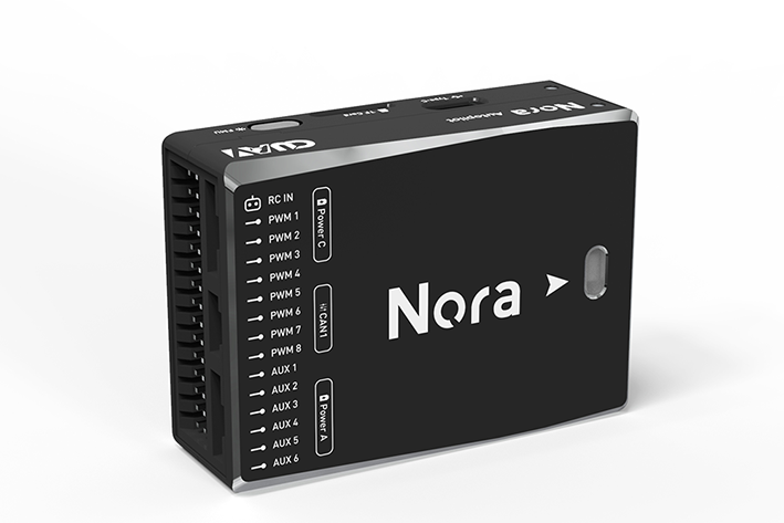
CUAV Nora
by CUAV
Community
Closed Hardware
PX4 currently exposes only eight PWM outputs on Nora while remaining channels await upstream support.
Key Specifications
Mounting Pattern
Custom
Connectivity
7 UARTs • 2 I²C • 2 CAN
Power
4.3–5.4 V • Power Module
Onboard Sensors
3× IMU • 2× Barometer • 1× Magnetometer
Firmware Support
Reference Docs
Detailed Specifications
Additional Features
Value-add capabilities bundled with the controller.- ✓ Built-in vibration isolation with temperature-compensated IMU platform
- ✓ Dual CAN buses supporting DroneCAN peripherals
- ✓ Triple IMU architecture for industrial reliability
Core Specifications
Quick reference for the primary hardware capabilities.
| MCU | Mounting | Custom | |
| Power | 4.3–5.4 V • Power Module | I/O Overview | 7 UARTs • 2 I²C • 2 CAN |
| PWM & Storage | 14 PWM outputs • microSD logging | Sensors | 3× IMU • 2× Barometer • 1× Magnetometer |
Hardware Overview
Core MCU, mounting, and mechanical data.
Base hardware specification
Default
| MCU | Mounting | Custom | |
| Dimensions | 46 × 64 × 22 mm | Weight | 75g |
Power Supply
Input rails, regulators, and redundancy. Voltage —
Inputs 4
Redundancy Redundant
Power Inputs
POWER1 Power Module
Connector:
6-pin power monitor
Voltage:
4.3–5.4 V
POWER2 Power Module
Connector:
6-pin power monitor
Voltage:
4.3–5.4 V
USB USB
Connector:
Micro-USB
Voltage:
4.75–5.25 V
SERVO_RAIL Servo Rail
Voltage:
0–36 V
Passthrough servo rail with high-voltage tolerance
| Input Voltage | — | Redundancy | ✓ Yes |
Dual power module inputs with DroneCAN battery interface allow triple-redundant supply paths.
Connectivity & I/O
Port availability, buses, and expansion options.| UARTs | 7 | CAN Bus | 2 |
| PWM Outputs | 14 | SD Card | ✓ Yes |
| Ethernet | ✗ No | ||
Peripheral Ports
| Port | Type | Default Function | Voltage / Level | Connector | Notes |
|---|---|---|---|---|---|
| TELEM1 | UART | Primary MAVLink telemetry | 3.3 V signal / 5 V supply | JST-GH 6-pin | High-current regulator powers telemetry radios with hardware flow control. |
| TELEM2 | UART | Secondary telemetry link | 3.3 V signal / 5 V supply | JST-GH 6-pin | Full RTS/CTS UART suitable for RTK corrections or redundant radios. |
| TELEM3 / UART4 | UART | Configurable payload UART | 3.3 V signal | JST-GH 6-pin | Additional serial port routed to expansion header for companion sensors or scripting engines. |
| Debug UART | UART | Console / SLCAN | 3.3 V signal | JST-GH 6-pin | Can be reassigned between console access, SLCAN, or serial RC via parameter mapping. |
| GPS1 | GPS | Primary GPS/compass/safety harness | 3.3 V signal / 5 V supply | JST-GH 10-pin | Integrates safety switch, buzzer, and I2C compass wiring for the first GNSS unit. |
| GPS2 | GPS | Secondary GPS | 3.3 V signal / 5 V supply | JST-GH 6-pin | Provides redundant GNSS interface or alternate UART/I2C combination. |
| CAN1 | CAN | DroneCAN peripheral bus | Differential CAN / 5 V supply | JST-GH 4-pin | Powered CAN-FD port for smart power modules or payloads. |
| CAN2 | CAN | Redundant DroneCAN bus | Differential CAN / 5 V supply | JST-GH 4-pin | Second CAN channel for ESC networks or redundant sensors. |
| I2C1 | I2C | External sensor bus | 3.3 V | JST-GH 4-pin | Dedicated I2C breakout for airspeed sensors or digital payloads. |
| I2C2 (GPS shared) | I2C | Compass via GPS harness | 3.3 V | JST-GH 10-pin/6-pin | SDA/SCL lines shared with GPS connectors for external magnetometers. |
| RCIN | RC | Serial RC input | 3.3 V signal / 5 V supply | JST-GH 6-pin | Supports SBUS, DSM, FPort, CRSF, and PPM receivers with RSSI breakout. |
| PWM OUT (1-14) | PWM | Motor and servo outputs | Servo rail (0-36 V tolerant) | Servo breakout | Fourteen PWM outputs with DShot capability on FMU-driven groups. |
| POWER1 | Power | Primary power module input | 4.3-5.4 V | 6-pin power monitor | Provides analog voltage/current telemetry and regulated 5 V supply. |
| POWER2 | Power | Secondary power module input | 4.3-5.4 V | 6-pin power monitor | Redundant power module input supporting DroneCAN smart batteries. |
| SERVO RAIL | Power | PWM servo supply | 0-36 V tolerant | Servo rail bus | High-voltage tolerant rail powering actuators independent of FMU logic. |
| Micro-USB | USB | Console and firmware updates | 5 V | Micro-USB | Provides SERIAL0 console, log access, and firmware flashing. |
| Buzzer/Safety | Other | External safety switch and buzzer | 5 V supply | JST harness | Combined harness powering the illuminated safety switch and high-output buzzer. |
Onboard Sensors
IMU, barometer, and magnetometer load-outs per revision.| IMU | |||
| Barometer | |||
| Magnetometer | |||
Known Issues & Advisories
BMI088 I²C driver produces unstable gyro data
PX4's bmi088_i2c driver reports severe gyro jitter and unusable orientation on Crazyflie and other I²C-based boards.
Medium
Reported
Affects Bosch Sensortec BMI088
Onboard IMU
ICM-20689 integral timing spikes under PX4
PX4 v1.12 builds show random accelerometer_integral_dt and gyro_integral_dt spikes on the ICM-20689, destabilising EKF attitude estimates.
Medium
Reported
Affects TDK InvenSense ICM-20689
Onboard IMU
Documentation & Vendor Resources
Contributors: dependabot[bot]
Last updated:
View History