Found an issue with this page?
Edit on GitHub
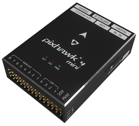
Holybro Pixhawk 4 Mini
by Holybro
Community
Open Hardware
PX4 documentation notes some production runs swap the BMI055 for an ICM20602 second IMU while maintaining identical interfaces.
Key Specifications
Mounting Pattern
Custom
Connectivity
5 UARTs • 2 I²C • 1 CAN
Power
4.75–5.5 V • Power Module
Onboard Sensors
2× IMU • 1× Barometer • 1× Magnetometer
Firmware Support
Reference Docs
Detailed Specifications
Additional Features
Value-add capabilities bundled with the controller.- ✓ FMUv5 mini form factor with 11 PWM outputs
- ✓ Redundant power inputs across POWER and USB rails
- ✓ Integrated microSD logging and external buzzer support
Core Specifications
Quick reference for the primary hardware capabilities.
| MCU | Mounting | Custom | |
| Power | 4.75–5.5 V • Power Module | I/O Overview | 5 UARTs • 2 I²C • 1 CAN |
| PWM & Storage | 11 PWM outputs • microSD logging | Sensors | 2× IMU • 1× Barometer • 1× Magnetometer |
Hardware Overview
Core MCU, mounting, and mechanical data.
Base hardware specification
Default
| MCU | Mounting | Custom | |
| Dimensions | 38 × 55 × 15.5 mm | Weight | 37.2g |
Power Supply
Input rails, regulators, and redundancy. Voltage —
Inputs 3
Redundancy Redundant
Power Inputs
POWER1 Power Module
Connector:
6-pin power monitor
Voltage:
4.75–5.5 V
POWER2 Power Module
Connector:
6-pin power monitor
Voltage:
4.75–5.5 V
USB USB
Connector:
Micro-USB
Voltage:
4.75–5.25 V
| Input Voltage | — | Redundancy | ✓ Yes |
Dual power domains with servo rail tolerant to 24V and POWER input protected up to 6V.
Connectivity & I/O
Port availability, buses, and expansion options.| UARTs | 5 | CAN Bus | 1 |
| PWM Outputs | 11 | SD Card | ✓ Yes |
| Ethernet | ✗ No | ||
Peripheral Ports
| Port | Type | Default Function | Voltage / Level | Connector | Notes |
|---|---|---|---|---|---|
| TELEM1 | UART | Primary MAVLink telemetry | 3.3 V signal / 5 V supply | JST-GH 6-pin | Provides hardware flow control and dedicated regulator for telemetry radios. |
| TELEM2 | UART | Secondary telemetry or companion link | 3.3 V signal / 5 V supply | JST-GH 6-pin | Full RTS/CTS UART for redundant radios or RC backhaul. |
| GPS | GPS | Combined GPS/compass harness | 3.3 V signal / 5 V supply | JST-GH 10-pin | Bundles GPS, external magnetometer, safety switch, and buzzer wiring. |
| CAN1 | CAN | DroneCAN bus | Differential CAN / 5 V supply | JST-GH 4-pin | Provides regulated power for DroneCAN peripherals or smart power modules. |
| I2C1 | I2C | External sensor bus | 3.3 V | JST-GH 4-pin | Shared with GPS harness for magnetometers or digital sensors. |
| I2C2 | I2C | Auxiliary I2C expansion | 3.3 V | JST-GH 4-pin | Secondary I2C connector for airspeed sensors or rangefinders. |
| RCIN | RC | Serial RC or PPM input | 3.3 V signal / 5 V supply | JST-GH 6-pin | Supports SBUS, DSM, and PPM receivers through dedicated harness. |
| FMU PWM OUT (1-8) | PWM | Primary motor outputs | Servo rail (0-24 V tolerant) | Servo rail bank A | FMU-controlled PWM outputs with DShot support on main groups. |
| AUX PWM OUT (9-11) | PWM | Auxiliary actuator outputs | Servo rail (0-24 V tolerant) | JST-GH breakout | Additional PWM pads for camera triggers, retracts, or tail servos. |
| POWER1 | Power | Primary power module input | 4.75-5.5 V | 6-pin power monitor | Supplies regulated 5 V and telemetry from the included PM07 power module. |
| POWER2 | Power | Secondary power module input | 4.75-5.5 V | 6-pin power monitor | Backup power module connection for redundant supply setups. |
| SERVO RAIL | Power | PWM servo supply | 0-24 V tolerant | Servo rail bus | High-voltage tolerant servo power rail isolated from FMU logic. |
| Micro-USB | USB | Console and firmware updates | 5 V | Micro-USB | Provides SERIAL0 console and bootloader access for configuration. |
| Buzzer/Safety | Other | External safety switch and buzzer | 5 V supply | JST harness | Shared harness powering the LED safety switch and piezo buzzer. |
Onboard Sensors
IMU, barometer, and magnetometer load-outs per revision.| IMU | |||
| Barometer | |||
| Magnetometer | |||
Known Issues & Advisories
ICM-20689 integral timing spikes under PX4
PX4 v1.12 builds show random accelerometer_integral_dt and gyro_integral_dt spikes on the ICM-20689, destabilising EKF attitude estimates.
Medium
Reported
Affects TDK InvenSense ICM-20689
Onboard IMU
Documentation & Vendor Resources
Contributors: dependabot[bot]
Last updated:
View History