Found an issue with this page?
Edit on GitHub
Holybro Pixhawk 4
by Holybro
Community
Open Hardware
Aluminum enclosure option increases weight to 49g but retains identical electronics.
Key Specifications
Mounting Pattern
Custom
Connectivity
6 UARTs • 2 I²C • 2 CAN
Power
4.9–5.5 V • Power Module
Onboard Sensors
2× IMU • 1× Barometer • 1× Magnetometer
Firmware Support
Reference Docs
Detailed Specifications
Additional Features
Value-add capabilities bundled with the controller.- ✓ Dual IMU stack with dedicated vibration isolation
- ✓ Two CAN buses and four I2C ports for expansion
- ✓ Integrated microSD slot for high-rate logging
Core Specifications
Quick reference for the primary hardware capabilities.
| MCU | Mounting | Custom | |
| Power | 4.9–5.5 V • Power Module | I/O Overview | 6 UARTs • 2 I²C • 2 CAN |
| PWM & Storage | 16 PWM outputs • microSD logging | Sensors | 2× IMU • 1× Barometer • 1× Magnetometer |
Hardware Overview
Core MCU, mounting, and mechanical data.
Base hardware specification
Default
| MCU | Mounting | Custom | |
| Dimensions | 44 × 84 × 12 mm | Weight | 33.3g |
Power Supply
Input rails, regulators, and redundancy. Voltage —
Inputs 3
Redundancy Redundant
Power Inputs
POWER1 Power Module
Connector:
6-pin power monitor
Voltage:
4.9–5.5 V
POWER2 Power Module
Connector:
6-pin power monitor
Voltage:
4.9–5.5 V
USB USB
Connector:
Micro-USB
Voltage:
4.75–5.25 V
| Input Voltage | — | Redundancy | ✓ Yes |
Triple-redundant power inputs with servo rail tolerant to 42V and POWER rails surviving up to 10V.
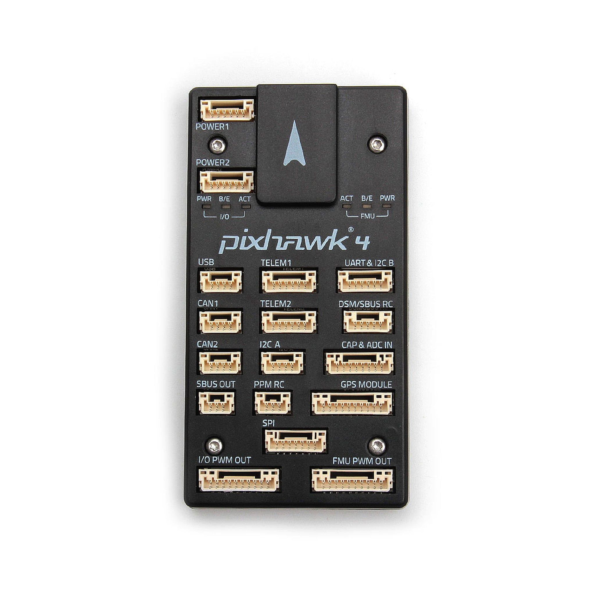
Connectivity & I/O
Port availability, buses, and expansion options.| UARTs | 6 | CAN Bus | 2 |
| PWM Outputs | 16 | SD Card | ✓ Yes |
| Ethernet | ✗ No | ||
Peripheral Ports
| Port | Type | Default Function | Voltage / Level | Connector | Notes |
|---|---|---|---|---|---|
| TELEM1 | UART | Primary MAVLink telemetry | 3.3 V signal / 5 V supply | JST-GH 6-pin | UART7 with hardware RTS/CTS and dedicated 5 V regulator for telemetry radios. |
| TELEM2 | UART | Secondary telemetry or companion link | 3.3 V signal / 5 V supply | JST-GH 6-pin | UART5 port with full flow control for redundant radios or RTK corrections. |
| GPS1 | GPS | Primary GPS/compass/safety harness | 3.3 V signal / 5 V supply | JST-GH 10-pin | Bundles GPS, magnetometer, safety switch, RGB LED, and buzzer wiring. |
| GPS2 | GPS | Secondary GPS | 3.3 V signal / 5 V supply | JST-GH 6-pin | Provides redundant GNSS receiver connection or RTK base link. |
| CAN1 | CAN | DroneCAN bus | Differential CAN / 5 V supply | JST-GH 4-pin | Supplies 5 V auxiliary power for smart modules or ESCs. |
| CAN2 | CAN | Redundant DroneCAN bus | Differential CAN / 5 V supply | JST-GH 4-pin | Second isolated CAN-FD port for peripherals or ESC networks. |
| I2C A | I2C | External sensor bus | 3.3 V | JST-GH 4-pin | Primary I2C port for airspeed sensors, rangefinders, or LED expanders. |
| I2C B | I2C | Auxiliary I2C expansion | 3.3 V | JST-GH 4-pin | Secondary I2C bus enabling multiple digital peripherals. |
| ADC | Analog | Analog sensing / airspeed input | 3.3 V reference | JST-GH 3-pin | Provides analog voltage input and ground/reference pins for sensors. |
| RCIN | RC | Serial RC or PPM input | 3.3 V signal / 5 V supply | JST-GH 6-pin | Supports SBUS, DSM, PPM, and FPort protocols via dedicated header. |
| S.BUS OUT / RSSI | RC | S.Bus passthrough and analog RSSI | 3.3 V signal | JST-GH 3-pin | Allows redundant receivers or servo expanders with RSSI feedback. |
| FMU PWM OUT (1-8) | PWM | Primary motor outputs | Servo rail (0-42 V tolerant) | Servo rail bank A | FMU-controlled outputs supporting DShot on grouped channels. |
| IO PWM OUT (9-16) | PWM | Auxiliary PWM outputs | Servo rail (0-42 V tolerant) | Servo rail bank B | IOMCU-managed outputs for additional actuators and payloads. |
| POWER1 | Power | Primary power module input | 4.9-5.5 V | 6-pin power monitor | Provides redundant 5 V supply with current and voltage telemetry. |
| POWER2 | Power | Secondary power module input | 4.9-5.5 V | 6-pin power monitor | Backup SMBus-enabled power module connection. |
| SERVO RAIL | Power | PWM servo supply | 0-42 V tolerant | Servo rail bus | High-voltage tolerant rail powering servos independently of FMU logic. |
| Micro-USB | USB | Console and firmware updates | 5 V | Micro-USB | Provides SERIAL0 console and bootloader access for configuration. |
| FMU Debug | Debug | SWD + console | 3.3 V | JST-GH 6-pin | Breaks out SWDIO/SWCLK and serial console for firmware development. |
Onboard Sensors
IMU, barometer, and magnetometer load-outs per revision.| IMU | |||
| Barometer | |||
| Magnetometer | |||
Known Issues & Advisories
ICM-20689 integral timing spikes under PX4
PX4 v1.12 builds show random accelerometer_integral_dt and gyro_integral_dt spikes on the ICM-20689, destabilising EKF attitude estimates.
Medium
Reported
Affects TDK InvenSense ICM-20689
Onboard IMU
Documentation & Vendor Resources
Contributors: dependabot[bot]
Last updated:
View History