Found an issue with this page?
Edit on GitHub
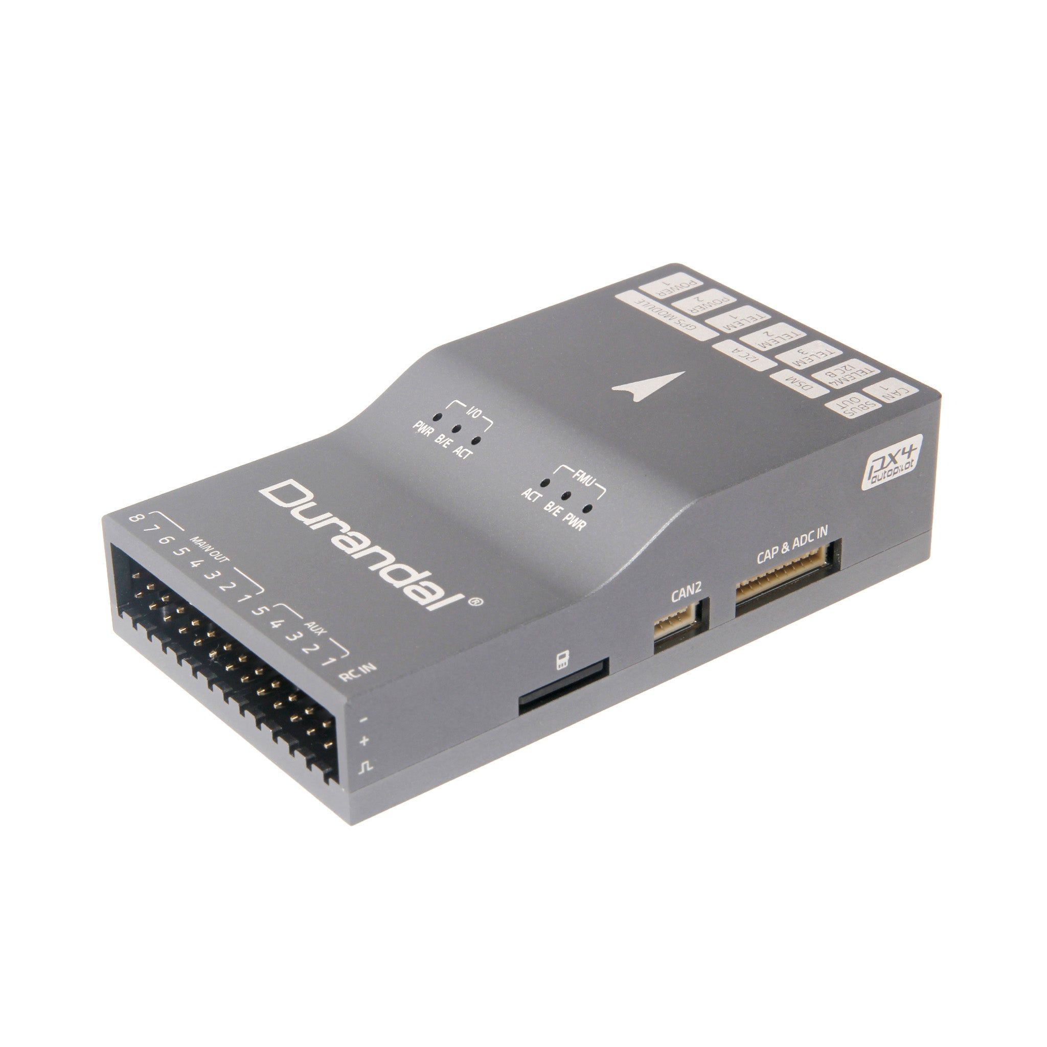
Holybro Durandal
by Holybro
Community
Closed Hardware
Additional PWM groups can be reassigned as GPIO, enabling flexible payload integration on large airframes.
Key Specifications
Mounting Pattern
Custom
Connectivity
6 UARTs • 2 I²C • 2 CAN
Power
4.9–5.5 V • Power Module
Onboard Sensors
2× IMU • 1× Barometer • 1× Magnetometer
Firmware Support
ArduPilot
PX4 Autopilot
Reference Docs
Detailed Specifications
Additional Features
Value-add capabilities bundled with the controller.- ✓ Built-in IMU heater for thermal stability
- ✓ Dual USB-C and JST-GH debug connectivity
- ✓ Integrated vibration damping chassis
Core Specifications
Quick reference for the primary hardware capabilities.
| MCU | Mounting | Custom | |
| Power | 4.9–5.5 V • Power Module | I/O Overview | 6 UARTs • 2 I²C • 2 CAN |
| PWM & Storage | 16 PWM outputs • microSD logging | Sensors | 2× IMU • 1× Barometer • 1× Magnetometer |
Hardware Overview
Core MCU, mounting, and mechanical data.
Base hardware specification
Default
| MCU | Mounting | Custom | |
| Dimensions | 45 × 80 × 20.5 mm | Weight | 64g |
Power Supply
Input rails, regulators, and redundancy. Voltage —
Inputs 4
Redundancy Redundant
Power Inputs
POWER1 Power Module
Connector:
6-pin power monitor
Voltage:
4.9–5.5 V
POWER2 Power Module
Connector:
6-pin power monitor
Voltage:
4.9–5.5 V
USB USB
Connector:
USB Type-C
Voltage:
4.75–5.25 V
SERVO_RAIL Servo Rail
Voltage:
0–36 V
High-voltage tolerant servo rail passthrough
| Input Voltage | — | Redundancy | ✓ Yes |
Dual power module inputs with over-current protection on peripheral rails.
Connectivity & I/O
Port availability, buses, and expansion options.| UARTs | 6 | CAN Bus | 2 |
| PWM Outputs | 16 | SD Card | ✓ Yes |
| Ethernet | ✗ No | ||
Peripheral Ports
| Port | Type | Default Function | Voltage / Level | Connector | Notes |
|---|---|---|---|---|---|
| TELEM1 | UART | Primary MAVLink telemetry | 3.3 V signal / 5 V supply | JST-GH 6-pin | Provides hardware flow control and high-current regulator for telemetry radios. |
| TELEM2 | UART | Secondary telemetry or payload link | 3.3 V signal / 5 V supply | JST-GH 6-pin | Second RTS/CTS-capable UART for redundant radios or RTK corrections. |
| GPS1 | GPS | Primary GPS/compass/safety harness | 3.3 V signal / 5 V supply | JST-GH 10-pin | Bundles GPS, magnetometer, safety switch, and buzzer wiring. |
| GPS2 | GPS | Secondary GPS | 3.3 V signal / 5 V supply | JST-GH 6-pin | Redundant GNSS receiver interface or RTK base link. |
| CAN1 | CAN | DroneCAN peripheral bus | Differential CAN / 5 V supply | JST-GH 4-pin | Powers DroneCAN accessories such as ESCs or smart modules. |
| CAN2 | CAN | Redundant DroneCAN bus | Differential CAN / 5 V supply | JST-GH 4-pin | Second CAN-FD interface for payload networks or redundant ESC chains. |
| I2C1 | I2C | External sensor bus | 3.3 V | JST-GH 4-pin | Primary I2C breakout for compasses, rangefinders, or payload sensors. |
| I2C2 | I2C | Auxiliary I2C expansion | 3.3 V | JST-GH 4-pin | Secondary bus supporting additional digital peripherals. |
| RCIN | RC | Serial RC or PPM input | 3.3 V signal / 5 V supply | JST-GH 6-pin | Supports SBUS, DSM, FPort, and legacy PPM receivers with dedicated RSSI pin. |
| FMU PWM OUT (1-8) | PWM | Primary motor outputs | Servo rail (0-36 V tolerant) | Servo breakout bank A | FMU-controlled outputs supporting high-rate DShot or PWM protocols. |
| IO PWM OUT (9-16) | PWM | Auxiliary PWM outputs | Servo rail (0-36 V tolerant) | Servo breakout bank B | IOMCU-managed outputs for secondary actuators, camera triggers, or landing gear. |
| POWER1 | Power | Primary power module input | 4.9-5.5 V | 6-pin power monitor | Provides redundant 5 V and current/voltage telemetry from the primary power module. |
| POWER2 | Power | Secondary power module input | 4.9-5.5 V | 6-pin power monitor | Secondary SMBus-enabled power input for redundancy. |
| SERVO RAIL | Power | PWM servo supply | 0-36 V tolerant | Servo rail bus | High-voltage tolerant servo rail isolated from FMU logic supply. |
| USB-C | USB | Console and firmware updates | 5 V | USB Type-C | Provides SERIAL0 console, bootloader, and log access. |
| FMU Debug | Debug | SWD + console | 3.3 V | JST-GH 6-pin | Offers SWDIO/SWCLK and UART console for development and diagnostics. |
| Buzzer/Safety | Other | External safety switch and buzzer | 5 V supply | JST harness | Combined harness powering the safety button, RGB LED, and high-output buzzer. |
Onboard Sensors
IMU, barometer, and magnetometer load-outs per revision.| IMU | |||
| Barometer | |||
| Magnetometer | |||
Known Issues & Advisories
BMI088 I²C driver produces unstable gyro data
PX4's bmi088_i2c driver reports severe gyro jitter and unusable orientation on Crazyflie and other I²C-based boards.
Medium
Reported
Affects Bosch Sensortec BMI088
Onboard IMU
ICM-20689 integral timing spikes under PX4
PX4 v1.12 builds show random accelerometer_integral_dt and gyro_integral_dt spikes on the ICM-20689, destabilising EKF attitude estimates.
Medium
Reported
Affects TDK InvenSense ICM-20689
Onboard IMU
Documentation & Vendor Resources
Contributors: dependabot[bot]
Last updated:
View History