Found an issue with this page?
Edit on GitHub
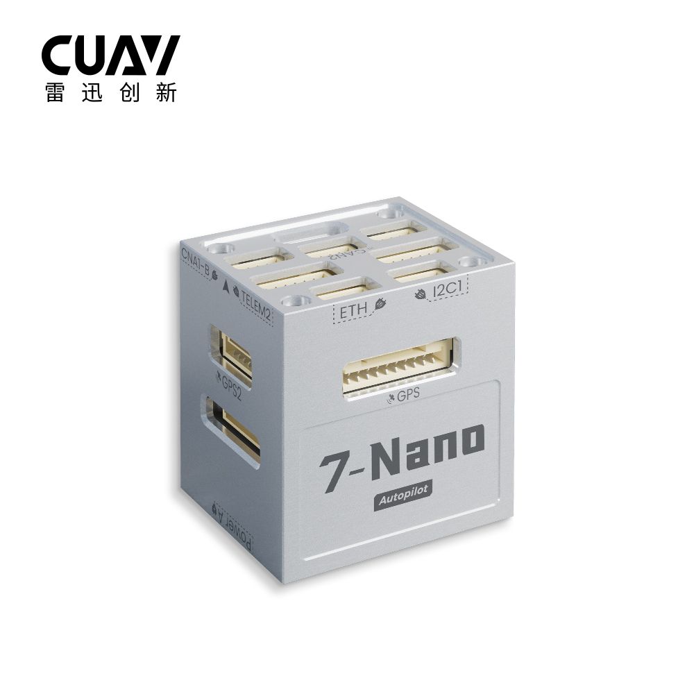
CUAV 7 Nano
by CUAV
Community
Closed Hardware
Built-in IST8310 magnetometer is often supplemented with an external compass to mitigate interference on the stack.
Key Specifications
Mounting Pattern
Custom
Connectivity
5 UARTs • 3 CAN
Power
Voltage range depends on connected power brick • Power Module
Onboard Sensors
2× IMU • 2× Barometer • 1× Magnetometer
Firmware Support
Detailed Specifications
Additional Features
Value-add capabilities bundled with the controller.- ✓ Integrated 100 Mbps Ethernet for onboard computer networking.
- ✓ Dual IMU stack with industrial temperature support and on-board IST8310 compass.
- ✓ 14 PWM outputs with GPIO-selectable 3.3 V or 5 V servo rail.
Core Specifications
Quick reference for the primary hardware capabilities.
| MCU | Mounting | Custom | |
| Power | Voltage range depends on connected power brick • Power Module | I/O Overview | 5 UARTs • 3 CAN |
| PWM & Storage | 14 PWM outputs • microSD logging | Sensors | 2× IMU • 2× Barometer • 1× Magnetometer |
Hardware Overview
Core MCU, mounting, and mechanical data.
Base hardware specification
Default
| MCU | Mounting | Custom |
Power Supply
Input rails, regulators, and redundancy. Voltage —
Inputs 1
Redundancy —
Power Inputs
Power A module Power Module
Connector:
6-pin
Voltage:
Voltage range depends on connected power brick
External module providing regulated flight controller power.
| Input Voltage | — | Redundancy | — |
Configurable 3.3V/5V servo rail with dedicated power monitor connector.
Connectivity & I/O
Port availability, buses, and expansion options.| UARTs | 5 | CAN Bus | 3 |
| PWM Outputs | 14 | SD Card | ✓ Yes |
| Ethernet | ✓ Yes | ||
Peripheral Ports
| Port | Type | Default Function | Voltage / Level | Connector | Notes |
|---|---|---|---|---|---|
| TELEM1 | UART | Primary MAVLink telemetry | 3.3 V signal / 5 V @ 1.5 A peripheral power | JST-GH 6-pin | High-current telemetry rail powering radios or companion computers with flow control. |
| TELEM2 | UART | Secondary telemetry or RTK link | 3.3 V signal / 5 V supply | JST-GH 6-pin | Full-duplex UART with RTS/CTS for redundant communications. |
| UART4 | UART | Auxiliary serial expansion | 3.3 V signal | JST-GH 6-pin | Configurable UART for scripting engines, serial RC, or payload telemetry. |
| GPS1 | GPS | Primary GPS/compass/safety harness | 3.3 V signal / 5 V supply | JST-GH 10-pin | Combines GNSS, safety switch, buzzer, and I2C compass wiring. |
| GPS2 | GPS | Secondary GPS or telemetry | 3.3 V signal / 5 V supply | JST-GH 6-pin | Redundant GNSS header sharing the external I2C bus. |
| CAN1 | CAN | DroneCAN peripheral bus | Differential CAN / 5 V supply | JST-GH 4-pin | Standard CAN-FD port for ESCs or payload nodes. |
| CAN2 | CAN | Redundant DroneCAN bus | Differential CAN / 5 V supply | JST-GH 4-pin | Second CAN-FD channel for redundant sensors. |
| CAN3 (Power) | CAN | CAN power module input | Differential CAN / 5 V supply | JST-GH 4-pin | Dedicated CAN port for CUAV CAN power module or smart battery interface. |
| RCIN | RC | Serial RC input | 3.3 V signal / 5 V supply | JST-GH 6-pin | Supports SBUS, CRSF, FPort, DSM, and PPM receivers through UART remapping. |
| PWM OUT (1-14) | PWM | Motor and servo outputs | Selectable 3.3/5 V signal (servo rail configurable) | Servo breakout | Fourteen outputs with DShot capability and configurable signal level jumpers. |
| POWER A | Power | Primary power module input | Regulated by external power brick | 6-pin power monitor | Supplies regulated 5 V and analog telemetry from the included power module. |
| SERVO RAIL | Power | PWM servo supply | Configurable 3.3/5 V (0-36 V tolerant) | Servo rail bus | Adjustable servo rail voltage using onboard jumpers for sensitive servos. |
| Ethernet | Ethernet | 100 Mbps companion link | 3.3 V logic | RJ45 breakout | Provides high-bandwidth networking for onboard computers. |
| USB-C | USB | Console and firmware updates | 5 V | USB Type-C | Primary configuration interface and log access point. |
| Buzzer/Safety | Other | External safety switch and buzzer | 5 V supply | JST harness | Combined harness powering safety switch, RGB LED, and buzzer assembly. |
Onboard Sensors
IMU, barometer, and magnetometer load-outs per revision.| IMU | |||
| Barometer | |||
| Magnetometer | |||
Known Issues & Advisories
BMI088 I²C driver produces unstable gyro data
PX4's bmi088_i2c driver reports severe gyro jitter and unusable orientation on Crazyflie and other I²C-based boards.
Medium
Reported
Affects Bosch Sensortec BMI088
Onboard IMU
Documentation & Vendor Resources
Contributors: dependabot[bot]
Last updated:
View History